
 СТАНЦИЯ ДАЛЬНЕЙ КОСМИЧЕСКОЙ СВЯЗИ.
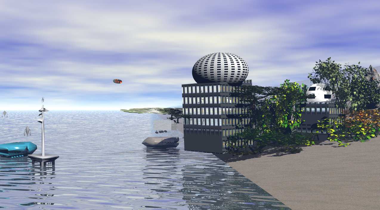
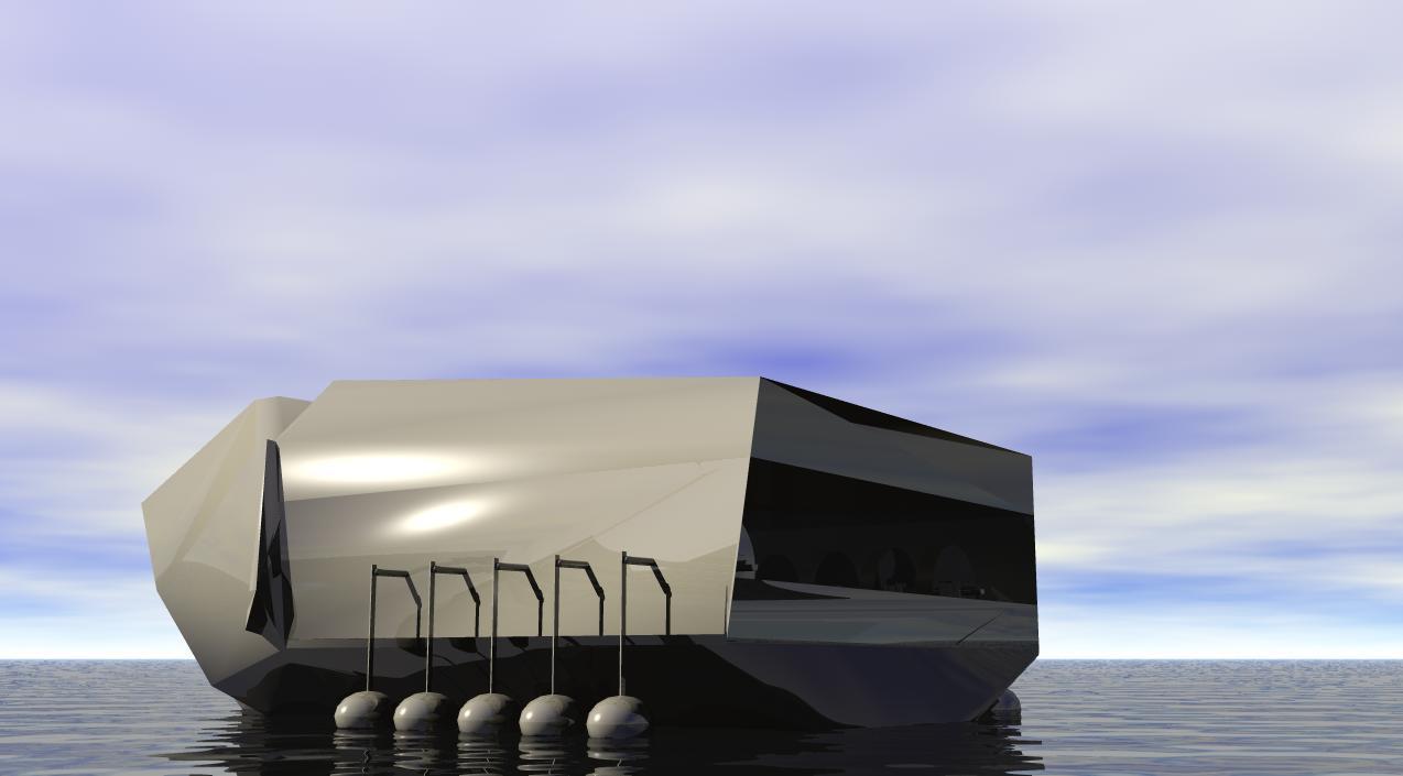
Энергообеспечение станции дальней космической связи и жилых объектов осуществляется с помощью волновых мобильных электростанций с десятью модулями, которые преобразуют энергию колебания волн в электроэнергию которая по кабелю передается на берег. Питание антенны сотовой связи и интернета происходит за счет встроенных модулей преобразования волн в установленную на дне платформу антенны. Опреснители морской воды используют электроэнергию модульных установок преобразования волн установленных, над водой платформах, вдоль побережья.Для обеспечения электроэнергией, в буи раннего предупреждения угрозы цунами, вмонтированы модули установки преобразующие энергию колебания волн в электроэнергию.
МОДУЛЬНАЯ УСТАНОВКА ПРЕОБРАЗОВАНИЯ ЭНЕРГИИ ВОЛН В ЭЛЕКТРОЭНЕРГИЮ С ДЕСЯТЬЮ МОДУЛЯМИ.
|
(21)(22) Заявка: 2018131614, 04.09.2018 (24) Дата начала отсчета срока действия патента: Дата регистрации: Приоритет(ы): (22) Дата подачи заявки: 04.09.2018 (45) Опубликовано: 02.03.2020 Бюл. № 7 (56) Список документов, цитированных в отчете о поиске: RU 2147077 C1, 27.03.2000. RU 2443900 C1, 27.02.2012. WO 2013157016 A1, 24.10.2013. US 2003091393 A1, 15.05.2003. US 2006028026 A1, 09.02.2006. Электронный адрес переписки: khromoff@yandex.ru |
(72) Автор(ы): (73) Патентообладатель(и): |
Р
РОССИЙСКАЯ ФЕДЕРАЦИЯ. ФЕДЕРАЛЬНАЯ СЛУЖБА ПО ИНТЕЛЛЕКТУАЛЬНОЙ СОБСТВЕННОСТИ (19) RU (11) 2 715 612 (13) C1 (51) МПК • F03B 13/16 (2006.01) (52) СПК • F03B 13/16 (2019.05) (12) ОПИСАНИЕ ИЗОБРЕТЕНИЯ К ПАТЕНТУ Статус: действует (последнее изменение статуса: 02.03.2020) (21)(22) Заявка: 2018131614, 04.09.2018 (24) Дата начала отсчета срока действия патента: 04.09.2018 Дата регистрации: 02.03.2020 Приоритет(ы): (22) Дата подачи заявки: 04.09.2018 (45) Опубликовано: 02.03.2020 Бюл. № 7 (56) Список документов, цитированных в отчете о поиске: RU 2147077 C1, 27.03.2000. RU 2443900 C1, 27.02.2012. WO 2013157016 A1, 24.10.2013. US 2003091393 A1, 15.05.2003. US 2006028026 A1, 09.02.2006. Электронный адрес переписки: khromoff@yandex.ru Александру (72) Автор(ы): Хромов Александр Васильевич (RU), Павлак Роман Альбинович (RU) (73) Патентообладатель(и): Хромов Александр Васильевич (RU), Павлак Роман Альбинович (RU) (54) МОДУЛЬНАЯ УСТАНОВКА ПРЕОБРАЗОВАНИЯ ЭНЕРГИИ ВОЛН В ЭЛЕКТРОЭНЕРГИЮ. MODULAR WAVE-TO-ELECTRIC POWER CONVERSION UNIT (57)
Реферат: Изобретение относится к гидроэнергетике, в частности к модульной установке преобразования энергии волн. Установка содержит основание 1 со стойками 2, поплавок на штанге, соединенный с валом 3 отбора мощности, на котором установлена муфта 8 для соединения с электрогенератором 10. Колебания рабочего тела передаются на вилку 11, внутри которой на валу 3 с вилкой 11 установлен храповой барабан 15, контактирующий зубьями с двумя собачками. Одна собачка установлена на вилке 11, другая - на основании 1. Внутри храпового барабана 15 установлена спиральная пружина 17, верхний конец которой закреплен на корпусе храпового барабана 14, нижний конец закреплен на валу 3. Вал 3 соединен с редуктором 9. Редуктор 9 соединен с электрогенератором 10. Изобретение направлено на обеспечение накопления кинетической энергии волн с последующим преобразованием в электроэнергию. 3 ил. Изобретение относится к гидроэнергетике, в частности к волновым энергетическим установкам, использующим энергию морских волн. Идея использования системы связанных плотов для использования энергии волн была предложена К.Э. Циолковским еще в 1935 году. В настоящее время известны работающие конструкции преобразователей энергии волн в электроэнергию. Среди них выделяются такие, как осциллирующая водяная колонна с воздушной турбиной Уэллса. Огромный буй-генератор РВ 150 длинной 42 метра с одиннадцатиметровым поплавком удерживаемый якорной системой. "Утка Солтера" это большое количество поплавков, связанных кинематически в цепь на одном валу, плавающих на поверхности воды. У всех преобразователей энергии волн можно найти недостатки, но основным достоинством всех этих конструкций является производство электроэнергии за счет энергии волн, при этом они не изменяют и не загрязняют окружающую среду. Приведенные примером конструкции устанавливают недалеко от берега на мелководье и фиксируют якорем или стойками на дне, причина течения, приливы и отливы, ветер. Электроэнергия, произведенная на волновой электростанции передается на берег по электрическому кабелю. Наиболее близкой к предлагаемой конструкции является разработанная в АО Белгородский завод энергетического машиностроения" Волновая энергетическая установка" (пат. RU 2147077 С1, кл. F03B 13/16), содержащая каркас с площадкой, блок шестерен и колес, вал отбора мощности соединенный через муфту с электрогенератором, поплавки на штангах. Представленная конструкция принята за прототип. К недостаткам данной установки следует отнести. Первое, отсутствие мобильности, данная установка крепится опорами к морскому дну. Второе, неравномерность вращения вала отбора мощности. Это происходит по причине того, что поплавки напрямую соединены посредством блока конических, цилиндрических зубчатых колес и шестерен с валом отбора мощности, а ускорение, передаваемое на поплавки потенциальной энергией волны, зависит от переменных величин: периода прохождения волн, а также от их длины и высоты. Третье, массивный маховик, предназначенный для стабилизации частоты вращения ротора электрогенератора и накопления энергии, при малой скорости вращения вала мощности, потерях от трения в подшипниках и об окружающий воздух не эффективен. Четвертое, установка имеет большую инерционность: поплавки, конические и цилиндрические зубчатые колеса, блок шестерен, вал отбора мощности, маховик все это испытывает разрушающие нагрузки при периодически возникающем ударе от кинетической энергии волны. Пятое, при большом волнении моря и крутой волне всю установку будет заливать водой, что приведет к коррозии металла и выходу из строя электрической части установки. Известное техническое решение не может обеспечить стабильное и эффективное преобразование энергии морских волн в энергию используемую потребителем на берегу или вдали от берега на больших глубинах. Энергия, возникающая при волновом движении воды в морях и океанах огромна и по плотности на 1 кв. м превышает ветровую энергию в 10 раз. Техническим результатом изобретения является возможность наиболее эффективно использовать энергию морских волн с помощью модульных установок преобразования энергии волн, установленных стационарно или на плавающем средстве и способных генерировать электроэнергию, используя для этого потенциальную энергию морских волн в любом месте волновой активности моря или океана, а в отсутствие волн генерировать электроэнергию, расходуя механическую энергию, накопленную в упругих пружинах. Предложенное изобретением техническое решение позволяет устранить вышеперечисленные недостатки известных прототипов и увеличить КПД установки, применив в качестве преобразователя и накопителя механической энергии упругую спиральную пружину. Указанный технический результат достигается тем, что в предлагаемой конструкции "Модульной установки преобразования энергии волн (МУПЭВ)" в электроэнергию, содержащей основание со стойками, поплавок на штанге, соединенный с валом отбора мощности, на котором установлена муфта для соединения с электрогенератором, согласно изобретению поплавок закрепленный стержнем на штанге, которая противоположным концом закреплена на вилке, внутри которой на общем валу с вилкой находится механический преобразователь и одновременно накопитель механической энергии, выполненный в виде корпуса барабана с закрепленными на нем двумя крышками с отверстиями в центре, в которые вставлен вал. Крышка, выполненная в виде храпового колеса, неподвижно закреплена на корпусе барабана. Храповое колесо и барабан представляют одно целое и эта деталь механизма называется храповой барабан. При необходимости храповой барабан можно изготовить, вырезая зубья храпового механизма непосредственно на корпусе барабана. Внутри храпового барабана упругая спиральная пружина наружным концом крепится к корпусу барабана, а внутренним концом к валу. Когда рабочее тело (вода) поднимает поплавок, стержень поднимает штангу и вилку. Закрепленная на вилке собачка входит в зацепление с храповым барабаном и вместе с ним поворачивает корпус барабана и верхний конец пружины, тем самым натягивает спиральную пружину внутри барабана. Собачка, закрепленная на основании, удерживает храповой барабан от возврата в исходное положение. Внутренний конец пружины упругой силой вращает вал, который опирается и свободно вращается внутри стоек, закрепленных на основании. Энергия колебания волн, пройдя через механический преобразователь и накопитель энергии, преобразуется в энергию вращения вала, который через муфту и повышающий обороты редуктор соединен с валом электрогенератора. Легкий и объемный поплавок обладает большой чувствительностью, малая полусфера реагирует на волны с невысоким гребнем волны, а большая полусфера поплавка не дает проваливаться в гребень волны, что позволяет передавать без потерь потенциальную энергию волны на штангу, которая легко поворачивает храповой барабан и через спиральную пружину внутри барабана, без кинетических толчков, плавно вращает вал отбора мощности. Стойки, закрепленные на основании, удерживают вал на определенной высоте и не позволяют валу, вилке и барабану смещаться в продольном направлении. Упругая спиральная пружина, КПД которой равен 0,96, верхним концом закреплена к корпусу храпового барабана, а нижним к валу отбора мощности. Барабан поворачивается и тянет за собой упругую спиральную пружину, которая передает крутящий момент на вал отбора мощности или сжимаясь накапливает избыточную механическую энергию. Конструкция вала отбора мощности предусматривает подсоединение к нему агрегатов и устройств потребляющих энергию вращения. Если вал отбора мощности МУПЭВ соединить с редуктором и через коробку передач, с валом гребного винта судна, то судно сможет передвигаться по воде, используя только энергию волны. Концы вала отбора мощности обработаны так, что на концах вала образованы одинаковые по длине, равные диаметру вала по ширине, разнонаправленные площадки, расположенные вдоль оси вала с отверстиями под крепление болтами. В данной конструкции левая площадка вала мощности предназначена для соединения с другой модульной установкой преобразования энергии волн. Установка модулей в ряд друг за другом на общий вал отбора мощности ограничено только размерами судна. Для большей устойчивости судна модули симметрично размещают по правому и по левому борту. Каждый добавленный модуль суммирует общую мощность установки. При необходимости, соединение производят с помощью карданной передачи. Правая площадка вала отбора мощности предназначена для соединения с валом, на котором находится предохранительная муфта, далее расположен повышающий обороты редуктор, соединенный с ротором электрогенератора. Предохранительная муфта предназначена для защиты от перегрузки предельной аккумулированной энергии пружин. Повышающий обороты редуктор позволяет поддерживать обороты вала оптимальные для работы электрогенератора. Размещение МУПЭВ в электроэнергию внутри судна или в закрытом боксе, позволяет использовать установку, не опасаясь угрозы повреждения водой. Штанга, стойка и поплавок вынесены за борт судна через овальное отверстие в борту и закрыто гибким, гидроизолирующим рукавом который крепится фланцем к борту, а к штанге хомутом. На Фиг. 1 показан общий вид модульной установки преобразования энергии волн в электроэнергию, разрез А-А, Фиг. 2 - вид сбоку, Фиг. 3 - вид сверху разрез Б-Б (см. Фиг. 1) Установка содержит основание 1, стойки 2 закреплены на основании 1, на стойках 2 лежит вал отбора мощности 3 закрепленный сверху крышкой 4 и 5. На валу проточены канавки, на которые надеты пружинные кольца 6 для фиксации вала 3 от продольного перемещения. Концы вала обработаны так, что на концах вала образованны одинаковые по размеру разнонаправленные площадки, расположенные вдоль оси вала, с местами под крепление болтами. Левая площадка с отверстиями предназначена для соединения с другим модулем волновой энергетической установки, что повышает суммарную мощность установки. Правая с резьбой под болты 7, для соединения с валом отбора мощности, на котором находится предохранительная муфта 8, далее расположен повышающий обороты редуктор 9 соединенный с валом электрогенератора 10. Вилка 11 (шатун) закрепленная крышками 12 и 13 на валу 3 свободно качается вверх вниз. Внутри вилки 11 на валу 3 установлен барабан, состоящий из корпуса 14 и крышки 15. Крышка барабана 15 выполнена в виде храпового колеса 16, которое закреплено болтами к корпусу 14. Внутри барабана 14 находиться лента спиральной пружины 17, верхний конец пружины закреплен на корпусе барабана 14 болтами 18, а другой конец пружины закреплен на валу 3 болтами 19. Под барабаном установлена стойка 20 закрепленная на основании 1. Внутри стойки 20 на оси 21 закреплена подпружиненная пружиной 22 собачка 23. Контактируя с храповым колесом 16, собачка 23 препятствует вращению корпуса барабана 14 в исходное состояние. Подпружиненная пружиной 24 собачка 25 установлена внутри вилки 11 на оси 26, контактируя с храповым колесом 16, вращает корпус барабана 14, поднятием вилки 11. На вилке 11 болтом 27 закреплена штанга 28. На конце штанги 28 в прорези на оси 29 установлен стержень 30, на который насажены поплавки 31 в виде полусфер разного размера. Место выхода штанги через борт судна выполнено в виде овального отверстия, с двух сторон герметично закрыто водонепроницаемыми эластичными рукавами, прикрепленными к борту фланцами, а на штанге закреплены хомутами. Модульная установка преобразования энергии волн в электроэнергию работает следующим образом. Данная установка размещается внутри судна, МУПЭВ с правым расположением штанги вдоль правого борта, МУПЭВ с левым расположением штанги вдоль левого борта и закрепляется на основании 1. Через овальное отверстие в борту штанга 28 выводиться за пределы судна, таким образом, чтобы поплавок 31 в отсутствии волн лежал на поверхности воды, а штанга 28 занимала горизонтальное положение. Когда к борту судна подходит гребень волны, вода поднимает поплавок 31 вверх, вместе с ним поднимается конец штанги 28, при этом другой конец штанги 28 вместе с вилкой 11, свободно поворачиваются на валу 3, поднимая вверх собачку 25. Собачка 25 входит в зацепление с храповым колесом 16, поворачивает храповой барабан 14, который натягивает пружину 17 и аккумулирует механическую энергию. Через упругую спиральную пружину 17 потенциальная энергия передается на вал 3, затем на муфту 8, через повышающий обороты редуктор 9 на электрогенератор 10. Гребень волны отошел от поплавка 31, образовалась впадина. Штанга 28 и поплавок 31 под собственной тяжестью падают вниз, при этом собачка 25 свободно скользит по храповому колесу, а собачка 22 наоборот, входит в зацепление с храповым колесом 16, не давая храповому барабану 14 вернуться в исходное положение. Следующая волна поднимает поплавок и весь процесс повторяется. Формула изобретения Модульная установка преобразования энергии волн, содержащая основание со стойками, поплавок на штанге, соединенный с валом отбора мощности, на котором установлена муфта, для соединения с электрогенератором, отличающаяся тем, что колебания рабочего тела передаются на вилку, внутри которой на общем валу с вилкой установлен храповой барабан, контактирующий зубьями с двумя собачками, одна установлена на вилке, другая на основании, а также спиральной пружиной внутри храпового барабана, верхний конец которой закреплен на корпусе храпового барабана, нижний конец закреплен на валу отбора мощности, на который нагружен редуктор, соединенный с электрогенератором.
MODULAR WAVE-TO-ELECTRIC POWER CONVERSION UNIT.
(57) Summary: The invention relates to hydropower, in particular, to the modular wave energy conversion unit. The unit contains a base 1 with racks 2, a float on a rod connected to the shaft 3 of the power take-off, on which a coupling 8 for connection to an electric generator 10 is installed. Oscillations of the working body are transferred to plug 11, inside of which on the shaft 3 with plug 11 is installed ratchet drum 15, contacting with teeth with two dogs. One dog is mounted on fork 11, the other - on the base 1. Inside the ratchet drum 15 installed a spiral spring 17, the upper end of which is mounted on the body of the ratchet drum 14, the lower end is mounted on the shaft 3. Shaft 3 is connected to the gearbox 9. Gearbox 9 is connected to the electric generator 10. The invention is aimed at ensuring the accumulation of wave kinetic energy with subsequent conversion into electricity. 3 slime. RESCUE BOAT POWER PLANT The invention relates to hydropower, in particular wave power plants using the energy of sea waves. The idea of using a system of coupled rafts to use wave energy was proposed by K.E. Tsiolkovsky back in 1935. Nowadays, there are known working constructions of wave energy converters to electricity. Among them stand out, such as an oscillating water column with an air turbine Wells. A huge 42-metre long PB 150 buoy-generator with an eleven-metre float held by an anchor system. "Salter's Duck" is a large number of floats kinematically chained on one shaft floating on the water surface. All wave energy transducers have flaws, but the main advantage of all these designs is that they produce electricity from wave energy without changing or polluting the environment. The above designs are installed not far from the shore in shallow water and fixed with an anchor or struts on the bottom, the cause of the current, tides and wind. Electric power generated by a wave power plant is transmitted ashore via an electric cable. The closest to the proposed design is the "Wave power plant" (patent RU 2147077 C1, tel. F03B 13/16), developed in Belgorod Power Engineering Plant JSC, which contains a frame with a platform, a block of gears and wheels, power take-off shaft connected through a clutch with an electric generator, floats on the rods. The presented design is taken as a prototype. The disadvantages of this installation should be attributed to. First of all, the lack of mobility, this unit is fixed by supports to the sea bottom. Secondly, the unevenness of the PTO shaft rotation. This is due to the fact that the floats are directly connected through a block of bevel, spur gears and pinion gears to the PTO shaft, and the acceleration transmitted to the floats by the potential wave energy depends on the variables: the period of wave passage, as well as their length and height. The third, massive flywheel, designed to stabilise the rotor speed of an electric generator and store energy, is not effective at low power shaft speeds, bearing friction losses and ambient air. Fourth, the unit has a high level of inertia: floats, bevel and spur gears, pinion block, power take-off shaft, flywheel, all this is subject to destructive loads when periodically occurring impact from kinetic wave energy. Fifth, in the event of a large sea wave and a steep wave, the entire unit will be flooded with water, resulting in metal corrosion and failure of the electrical part of the unit. A known technical solution cannot ensure the stable and efficient conversion of sea wave energy into energy used by the consumer on shore or away from shore at great depths. The energy generated by the wave motion of water in the seas and oceans is huge and in terms of density per square meter exceeds wind energy by 10 times. The technical result of the invention is the ability to make the most efficient use of sea wave energy with the help of modular wave energy conversion units installed stationary or on a floating medium and capable of generating electricity using the potential energy of sea waves anywhere in the wave activity of the sea or ocean, and in the absence of waves to generate electricity using the mechanical energy stored in elastic springs. The technical solution proposed by the invention allows to eliminate the above mentioned disadvantages of the known prototypes and to increase the efficiency of the unit by using the elastic spiral spring as a converter and a mechanical energy accumulator. The specified technical result is achieved by the fact that in the proposed design of the "Modular Wave Energy Conversion Unit (MUPEV)" into electricity, containing a base with racks, a float on a rod connected to a power take-off shaft, on which a coupling for connection to an electric generator is installed, according to the invention of the float fixed with a rod on the rod, which is fixed with the opposite end on a fork, inside which on a common shaft with a fork there is a mechanical converter and simultaneously a mechanical energy accumulator. The cover, which is made in the form of a ratchet wheel, is fixed to the drum body. The ratchet wheel and drum represent one whole and this part of the mechanism is called a ratchet drum. If necessary, the ratchet drum can be made by cutting out the teeth of the ratchet mechanism directly on the drum body. Inside the ratchet drum, an elastic spiral spring is mounted with the outer end to the drum body and the inner end to the shaft. When the working body (water) lifts the float, the rod lifts the rod and fork. The dog mounted on the fork enters the ratchet drum mesh and together with it rotates the drum body and the upper end of the spring, thus tightening the spiral spring inside the drum. The doggy mounted on the base keeps the ratchet drum from returning to its original position. The inner end of the spring elastically rotates the shaft, which rests and rotates freely inside the posts attached to the base. The oscillating energy of the waves, passing through a mechanical converter and energy storage device, is converted into the energy of the shaft rotation, which is connected to the shaft of the electric generator via a coupling and a gearbox that increases the speed. Lightweight and volumetric float has a high sensitivity, the small hemisphere reacts to waves with a low wave crest, and a large hemisphere float does not let fall into the wave crest, which allows you to transfer without loss of potential wave energy to the rod, which easily rotates the ratchet drum and through the spiral spring inside the drum, without kinetic shocks, smoothly rotates the PTO shaft. Stands attached to the base keep the shaft at a certain height and prevent the shaft, fork and drum from moving in a longitudinal direction. The elastic spiral spring, which has an efficiency of 0.96, is attached to the ratchet drum body with its upper end and the lower end to the PTO shaft. The drum turns and pulls the elastic spiral spring, which transfers the torque to the PTO shaft or compresses it to accumulate excess mechanical energy. The PTO shaft is designed to be connected to units and devices that consume power from rotation. If the PTO shaft is connected to the gearbox and through the gearbox to the propeller shaft of the ship, the ship can move through the water using only the wave energy. The PTO shaft ends are processed in such a way that the ends of the shaft are of the same length, equal in width to the shaft diameter, and have misaligned pads located along the shaft axis with bolt holes. In this design, the left shaft platform is designed to connect to another modular wave energy conversion unit. The installation of the modules, one after the other, on a common PTO shaft is limited only by the size of the vessel. For greater vessel stability, the modules are symmetrically placed on the starboard and starboard sides. Each added module sums up the total power of the plant. If necessary, the connection is made by means of a cardan gear. The right side of the PTO shaft is designed to be connected to the shaft on which the safety clutch is located, then there is a speeding gearbox connected to the generator rotor. The safety clutch is designed to protect the maximum stored energy of the springs from overloading. The speed boosting gearbox allows to keep the shaft speed optimal for the electric generator operation. Placement of the MUPEV in the electric power inside the vessel or in a closed box allows to use the unit without fear of water damage. The boom, prop and float are carried overboard through the oval opening in the vessel and closed by a flexible, waterproofing sleeve which is attached to the flange to the board and to the boom by a clamp. Fig. 1 shows the general view of the modular wave energy-to-power conversion unit, section A-A, Fig. 2 - side view, Fig. 3 - top view of section B-B (see Fig. 1). The unit contains a base 1, the posts 2 are fixed on the base 1, the PTO shaft 3 is fixed on the posts 2 with the cover 4 and 5 on top. There are grooves on the shaft, on which spring rings 6 are put to fix the shaft 3 from longitudinal movement. The shaft ends are machined in such a way that the ends of the shaft are formed by the same size omnidirectional areas, located along the shaft axis, with places under the bolts. The left-hand platform with holes is designed to connect to another module of the wave power plant, which increases the total power of the plant. The right one with bolt-on threads 7, for connection to the PTO shaft, on which the safety coupling 8 is located, then there is a gearbox 9 connected to the generator shaft 10. Plug 11 (connecting rod) fixed with lids 12 and 13 on shaft 3 swings freely up and down. Inside the plug 11 on shaft 3 there is a drum consisting of housing 14 and lid 15. Drum cover 15 is made in the form of a ratchet wheel 16, which is bolted to the body 14. Inside the drum 14 is a spiral spring tape 17, the upper end of the spring is fixed to the drum body 14 bolts 18, and the other end of the spring is fixed to the shaft 3 bolts 19. Under the drum there is a rack 20 fixed on the base 1. Inside the rack 20 on the axle 21 is mounted spring loaded 22 dog 23. Contacts with the ratchet wheel 16, dog 23 prevents rotation of the body of the drum 14 in its original state. Spring-loaded 24 dog 25 is mounted inside fork 11 on axis 26, contacting the ratchet wheel 16, rotates the drum body 14, lifting the fork 11. On the fork 11 with a bolt 27 the rod 28 is fixed. At the end of the rod 28 in the slots on the axis 29 rod 30 is mounted, on which floats 31 are mounted in the form of hemispheres of different sizes. The place of the rod exit through the board of the vessel is made in the form of an oval hole, on both sides it is hermetically sealed with waterproof elastic sleeves attached to the board with flanges, and on the rod are fixed with clamps. The Modular Wave-to-Energy Conversion Unit works as follows. This unit is placed inside the vessel, MUPEV with the right boom arrangement along the starboard, MUPEV with the left boom arrangement along the left side and fixed on the base 1. Through the oval aperture in the rod 28, the float 31 will lie on the water surface in the absence of waves and the rod 28 will take a horizontal position. When the crest of the wave approaches the vessel, the water raises the float 31 upwards, the end of the rod 28 rises with it, while the other end of the rod 28 together with the fork 11 turns freely on the shaft 3, raising the dog 25. Dog 25 enters the gear with ratchet wheel 16, turns the ratchet drum 14, which stretches the spring 17 and accumulates mechanical energy. Through the elastic spiral spring 17 potential energy is transferred to the shaft 3, then to the clutch 8, through the speeding gear 9 to the electric generator 10. The crest of the wave departed from float 31, a trough was formed. Boom 28 and float 31 under its own gravity fall down, with the dog 25 slides freely on the ratchet wheel, and the dog 22 on the contrary, enters into a gear with a ratchet wheel 16, not giving the ratchet drum 14 to return to its original position. The next wave raises the float and the whole process is repeated. The formula for the invention Modular wave energy conversion unit, containing a base with racks, float on the rod, connected to the PTO shaft, on which the coupling is installed, for connection with an electric generator, characterized by the fact that the vibrations of the working body is transmitted to the fork, inside which on a common shaft with the fork installed ratchet drum, contacting teeth with two dogs, one mounted on the fork, the other on the base and a spiral spring inside the ratchet drum, the upper end of which is mounted on the body of the ratchet drum, the lower end is mounted on the PTO shaft on which the gearbox connected to the electric generator is loaded. The boom, prop and float are carried overboard through the oval opening in the vessel and closed by a flexible, waterproofing sleeve which is attached to the flange to the board and to the boom by a clamp. Fig. 1 shows the general view of the modular wave energy-to-power conversion unit, section A-A, Fig. 2 - side view, Fig. 3 - top view of section B-B (see Fig. 1). The unit contains a base 1, the posts 2 are fixed on the base 1, the PTO shaft 3 is fixed on the posts 2 with the cover 4 and 5 on top. There are grooves on the shaft, on which spring rings 6 are put to fix the shaft 3 from longitudinal movement. The shaft ends are machined in such a way that the ends of the shaft are formed by the same size omnidirectional areas, located along the shaft axis, with places under the bolts. The left-hand platform with holes is designed to connect to another module of the wave power plant, which increases the total power of the plant. The right one with bolt-on threads 7, for connection to the PTO shaft, on which the safety coupling 8 is located, then there is a gearbox 9 connected to the generator shaft 10. Plug 11 (connecting rod) fixed with lids 12 and 13 on shaft 3 swings freely up and down. Inside the plug 11 on shaft 3 there is a drum consisting of housing 14 and lid 15. Drum cover 15 is made in the form of a ratchet wheel 16, which is bolted to the body 14. Inside the drum 14 is a spiral spring tape 17, the upper end of the spring is fixed to the drum body 14 bolts 18, and the other end of the spring is fixed to the shaft 3 bolts 19. Under the drum there is a rack 20 fixed on the base 1. Inside the rack 20 on the axle 21 is mounted spring loaded 22 dog 23. Contacts with the ratchet wheel 16, dog 23 prevents rotation of the body of the drum 14 in its original state. Spring-loaded 24 dog 25 is mounted inside fork 11 on axis 26, contacting the ratchet wheel 16, rotates the drum body 14, lifting the fork 11. On the fork 11 with a bolt 27 the rod 28 is fixed. At the end of the rod 28 in the slots on the axis 29 rod 30 is mounted, on which floats 31 are mounted in the form of hemispheres of different sizes. The place of the rod exit through the board of the vessel is made in the form of an oval hole, on both sides it is hermetically sealed with waterproof elastic sleeves attached to the board with flanges, and on the rod are fixed with clamps. The Modular Wave-to-Energy Conversion Unit works as follows. This unit is placed inside the vessel, MUPEV with the right boom arrangement along the starboard, MUPEV with the left boom arrangement along the left side and fixed on the base 1. Through the oval aperture in the rod 28, the float 31 will lie on the water surface in the absence of waves and the rod 28 will take a horizontal position. When the crest of the wave approaches the vessel, the water raises the float 31 upwards, the end of the rod 28 rises with it, while the other end of the rod 28 together with the fork 11 turns freely on the shaft 3, raising the dog 25. Dog 25 enters the gear with ratchet wheel 16, turns the ratchet drum 14, which stretches the spring 17 and accumulates mechanical energy. Through the elastic spiral spring 17 potential energy is transferred to the shaft 3, then to the clutch 8, through the speeding gear 9 to the electric generator 10. The crest of the wave departed from float 31, a trough was formed. Boom 28 and float 31 under its own gravity fall down, with the dog 25 slides freely on the ratchet wheel, and the dog 22 on the contrary, enters into a gear with a ratchet wheel 16, not giving the ratchet drum 14 to return to its original position. The next wave raises the float and the whole process is repeated. The formula for the invention Modular wave energy conversion unit, containing a base with racks, float on the rod, connected to the PTO shaft, on which the coupling is installed, for connection with an electric generator, characterized by the fact that the vibrations of the working body is transmitted to the fork, inside which on a common shaft with the fork installed ratchet drum, contacting teeth with two dogs, one mounted on the fork, the other on the base and a spiral spring inside the ratchet drum, the upper end of which is mounted on the body of the ratchet drum, the lower end is mounted on the PTO shaft on which the gearbox connected to the electric