
3d image mobiie wave power plants with ten modules and two power generators.
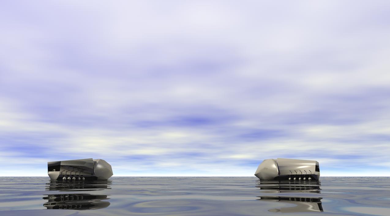
3D MODEL
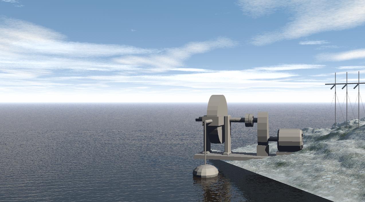
MODULAR WAVE-TO-ELECTRIC POWER CONVERSION UNIT.
(57) Summary: The invention relates to hydropower, in particular, to the modular wave energy conversion unit. The unit contains a base 1 with racks 2, a float on a rod connected to the shaft 3 of the power take-off, on which a coupling 8 for connection to an electric generator 10 is installed. Oscillations of the working body are transferred to plug 11, inside of which on the shaft 3 with plug 11 is installed ratchet drum 15, contacting with teeth with two dogs. One dog is mounted on fork 11, the other - on the base 1. Inside the ratchet drum 15 installed a spiral spring 17, the upper end of which is mounted on the body of the ratchet drum 14, the lower end is mounted on the shaft 3. Shaft 3 is connected to the gearbox 9. Gearbox 9 is connected to the electric generator 10. The invention is aimed at ensuring the accumulation of wave kinetic energy with subsequent conversion into electricity. 3 slime. RESCUE BOAT POWER PLANT The invention relates to hydropower, in particular wave power plants using the energy of sea waves. The idea of using a system of coupled rafts to use wave energy was proposed by K.E. Tsiolkovsky back in 1935. Nowadays, there are known working constructions of wave energy converters to electricity. Among them stand out, such as an oscillating water column with an air turbine Wells. A huge 42-metre long PB 150 buoy-generator with an eleven-metre float held by an anchor system. "Salter's Duck" is a large number of floats kinematically chained on one shaft floating on the water surface. All wave energy transducers have flaws, but the main advantage of all these designs is that they produce electricity from wave energy without changing or polluting the environment. The above designs are installed not far from the shore in shallow water and fixed with an anchor or struts on the bottom, the cause of the current, tides and wind. Electric power generated by a wave power plant is transmitted ashore via an electric cable. The closest to the proposed design is the "Wave power plant" (patent RU 2147077 C1, tel. F03B 13/16), developed in Belgorod Power Engineering Plant JSC, which contains a frame with a platform, a block of gears and wheels, power take-off shaft connected through a clutch with an electric generator, floats on the rods. The presented design is taken as a prototype. The disadvantages of this installation should be attributed to. First of all, the lack of mobility, this unit is fixed by supports to the sea bottom. Secondly, the unevenness of the PTO shaft rotation. This is due to the fact that the floats are directly connected through a block of bevel, spur gears and pinion gears to the PTO shaft, and the acceleration transmitted to the floats by the potential wave energy depends on the variables: the period of wave passage, as well as their length and height. The third, massive flywheel, designed to stabilise the rotor speed of an electric generator and store energy, is not effective at low power shaft speeds, bearing friction losses and ambient air. Fourth, the unit has a high level of inertia: floats, bevel and spur gears, pinion block, power take-off shaft, flywheel, all this is subject to destructive loads when periodically occurring impact from kinetic wave energy. Fifth, in the event of a large sea wave and a steep wave, the entire unit will be flooded with water, resulting in metal corrosion and failure of the electrical part of the unit. A known technical solution cannot ensure the stable and efficient conversion of sea wave energy into energy used by the consumer on shore or away from shore at great depths. The energy generated by the wave motion of water in the seas and oceans is huge and in terms of density per square meter exceeds wind energy by 10 times. The technical result of the invention is the ability to make the most efficient use of sea wave energy with the help of modular wave energy conversion units installed stationary or on a floating medium and capable of generating electricity using the potential energy of sea waves anywhere in the wave activity of the sea or ocean, and in the absence of waves to generate electricity using the mechanical energy stored in elastic springs. The technical solution proposed by the invention allows to eliminate the above mentioned disadvantages of the known prototypes and to increase the efficiency of the unit by using the elastic spiral spring as a converter and a mechanical energy accumulator. The specified technical result is achieved by the fact that in the proposed design of the "Modular Wave Energy Conversion Unit (MUPEV)" into electricity, containing a base with racks, a float on a rod connected to a power take-off shaft, on which a coupling for connection to an electric generator is installed, according to the invention of the float fixed with a rod on the rod, which is fixed with the opposite end on a fork, inside which on a common shaft with a fork there is a mechanical converter and simultaneously a mechanical energy accumulator. The cover, which is made in the form of a ratchet wheel, is fixed to the drum body. The ratchet wheel and drum represent one whole and this part of the mechanism is called a ratchet drum. If necessary, the ratchet drum can be made by cutting out the teeth of the ratchet mechanism directly on the drum body. Inside the ratchet drum, an elastic spiral spring is mounted with the outer end to the drum body and the inner end to the shaft. When the working body (water) lifts the float, the rod lifts the rod and fork. The dog mounted on the fork enters the ratchet drum mesh and together with it rotates the drum body and the upper end of the spring, thus tightening the spiral spring inside the drum. The doggy mounted on the base keeps the ratchet drum from returning to its original position. The inner end of the spring elastically rotates the shaft, which rests and rotates freely inside the posts attached to the base. The oscillating energy of the waves, passing through a mechanical converter and energy storage device, is converted into the energy of the shaft rotation, which is connected to the shaft of the electric generator via a coupling and a gearbox that increases the speed. Lightweight and volumetric float has a high sensitivity, the small hemisphere reacts to waves with a low wave crest, and a large hemisphere float does not let fall into the wave crest, which allows you to transfer without loss of potential wave energy to the rod, which easily rotates the ratchet drum and through the spiral spring inside the drum, without kinetic shocks, smoothly rotates the PTO shaft. Stands attached to the base keep the shaft at a certain height and prevent the shaft, fork and drum from moving in a longitudinal direction. The elastic spiral spring, which has an efficiency of 0.96, is attached to the ratchet drum body with its upper end and the lower end to the PTO shaft. The drum turns and pulls the elastic spiral spring, which transfers the torque to the PTO shaft or compresses it to accumulate excess mechanical energy. The PTO shaft is designed to be connected to units and devices that consume power from rotation. If the PTO shaft is connected to the gearbox and through the gearbox to the propeller shaft of the ship, the ship can move through the water using only the wave energy. The PTO shaft ends are processed in such a way that the ends of the shaft are of the same length, equal in width to the shaft diameter, and have misaligned pads located along the shaft axis with bolt holes. In this design, the left shaft platform is designed to connect to another modular wave energy conversion unit. The installation of the modules, one after the other, on a common PTO shaft is limited only by the size of the vessel. For greater vessel stability, the modules are symmetrically placed on the starboard and starboard sides. Each added module sums up the total power of the plant. If necessary, the connection is made by means of a cardan gear. The right side of the PTO shaft is designed to be connected to the shaft on which the safety clutch is located, then there is a speeding gearbox connected to the generator rotor. The safety clutch is designed to protect the maximum stored energy of the springs from overloading. The speed boosting gearbox allows to keep the shaft speed optimal for the electric generator operation. Placement of the MUPEV in the electric power inside the vessel or in a closed box allows to use the unit without fear of water damage. The boom, prop and float are carried overboard through the oval opening in the vessel and closed by a flexible, waterproofing sleeve which is attached to the flange to the board and to the boom by a clamp. Fig. 1 shows the general view of the modular wave energy-to-power conversion unit, section A-A, Fig. 2 - side view, Fig. 3 - top view of section B-B (see Fig. 1). The unit contains a base 1, the posts 2 are fixed on the base 1, the PTO shaft 3 is fixed on the posts 2 with the cover 4 and 5 on top. There are grooves on the shaft, on which spring rings 6 are put to fix the shaft 3 from longitudinal movement. The shaft ends are machined in such a way that the ends of the shaft are formed by the same size omnidirectional areas, located along the shaft axis, with places under the bolts. The left-hand platform with holes is designed to connect to another module of the wave power plant, which increases the total power of the plant. The right one with bolt-on threads 7, for connection to the PTO shaft, on which the safety coupling 8 is located, then there is a gearbox 9 connected to the generator shaft 10. Plug 11 (connecting rod) fixed with lids 12 and 13 on shaft 3 swings freely up and down. Inside the plug 11 on shaft 3 there is a drum consisting of housing 14 and lid 15. Drum cover 15 is made in the form of a ratchet wheel 16, which is bolted to the body 14. Inside the drum 14 is a spiral spring tape 17, the upper end of the spring is fixed to the drum body 14 bolts 18, and the other end of the spring is fixed to the shaft 3 bolts 19. Under the drum there is a rack 20 fixed on the base 1. Inside the rack 20 on the axle 21 is mounted spring loaded 22 dog 23. Contacts with the ratchet wheel 16, dog 23 prevents rotation of the body of the drum 14 in its original state. Spring-loaded 24 dog 25 is mounted inside fork 11 on axis 26, contacting the ratchet wheel 16, rotates the drum body 14, lifting the fork 11. On the fork 11 with a bolt 27 the rod 28 is fixed. At the end of the rod 28 in the slots on the axis 29 rod 30 is mounted, on which floats 31 are mounted in the form of hemispheres of different sizes. The place of the rod exit through the board of the vessel is made in the form of an oval hole, on both sides it is hermetically sealed with waterproof elastic sleeves attached to the board with flanges, and on the rod are fixed with clamps. The Modular Wave-to-Energy Conversion Unit works as follows. This unit is placed inside the vessel, MUPEV with the right boom arrangement along the starboard, MUPEV with the left boom arrangement along the left side and fixed on the base 1. Through the oval aperture in the rod 28, the float 31 will lie on the water surface in the absence of waves and the rod 28 will take a horizontal position. When the crest of the wave approaches the vessel, the water raises the float 31 upwards, the end of the rod 28 rises with it, while the other end of the rod 28 together with the fork 11 turns freely on the shaft 3, raising the dog 25. Dog 25 enters the gear with ratchet wheel 16, turns the ratchet drum 14, which stretches the spring 17 and accumulates mechanical energy. Through the elastic spiral spring 17 potential energy is transferred to the shaft 3, then to the clutch 8, through the speeding gear 9 to the electric generator 10. The crest of the wave departed from float 31, a trough was formed. Boom 28 and float 31 under its own gravity fall down, with the dog 25 slides freely on the ratchet wheel, and the dog 22 on the contrary, enters into a gear with a ratchet wheel 16, not giving the ratchet drum 14 to return to its original position. The next wave raises the float and the whole process is repeated. The formula for the invention Modular wave energy conversion unit, containing a base with racks, float on the rod, connected to the PTO shaft, on which the coupling is installed, for connection with an electric generator, characterized by the fact that the vibrations of the working body is transmitted to the fork, inside which on a common shaft with the fork installed ratchet drum, contacting teeth with two dogs, one mounted on the fork, the other on the base and a spiral spring inside the ratchet drum, the upper end of which is mounted on the body of the ratchet drum, the lower end is mounted on the PTO shaft on which the gearbox connected to the electric generator is loaded. The boom, prop and float are carried overboard through the oval opening in the vessel and closed by a flexible, waterproofing sleeve which is attached to the flange to the board and to the boom by a clamp. Fig. 1 shows the general view of the modular wave energy-to-power conversion unit, section A-A, Fig. 2 - side view, Fig. 3 - top view of section B-B (see Fig. 1). The unit contains a base 1, the posts 2 are fixed on the base 1, the PTO shaft 3 is fixed on the posts 2 with the cover 4 and 5 on top. There are grooves on the shaft, on which spring rings 6 are put to fix the shaft 3 from longitudinal movement. The shaft ends are machined in such a way that the ends of the shaft are formed by the same size omnidirectional areas, located along the shaft axis, with places under the bolts. The left-hand platform with holes is designed to connect to another module of the wave power plant, which increases the total power of the plant. The right one with bolt-on threads 7, for connection to the PTO shaft, on which the safety coupling 8 is located, then there is a gearbox 9 connected to the generator shaft 10. Plug 11 (connecting rod) fixed with lids 12 and 13 on shaft 3 swings freely up and down. Inside the plug 11 on shaft 3 there is a drum consisting of housing 14 and lid 15. Drum cover 15 is made in the form of a ratchet wheel 16, which is bolted to the body 14. Inside the drum 14 is a spiral spring tape 17, the upper end of the spring is fixed to the drum body 14 bolts 18, and the other end of the spring is fixed to the shaft 3 bolts 19. Under the drum there is a rack 20 fixed on the base 1. Inside the rack 20 on the axle 21 is mounted spring loaded 22 dog 23. Contacts with the ratchet wheel 16, dog 23 prevents rotation of the body of the drum 14 in its original state. Spring-loaded 24 dog 25 is mounted inside fork 11 on axis 26, contacting the ratchet wheel 16, rotates the drum body 14, lifting the fork 11. On the fork 11 with a bolt 27 the rod 28 is fixed. At the end of the rod 28 in the slots on the axis 29 rod 30 is mounted, on which floats 31 are mounted in the form of hemispheres of different sizes. The place of the rod exit through the board of the vessel is made in the form of an oval hole, on both sides it is hermetically sealed with waterproof elastic sleeves attached to the board with flanges, and on the rod are fixed with clamps. The Modular Wave-to-Energy Conversion Unit works as follows. This unit is placed inside the vessel, MUPEV with the right boom arrangement along the starboard, MUPEV with the left boom arrangement along the left side and fixed on the base 1. Through the oval aperture in the rod 28, the float 31 will lie on the water surface in the absence of waves and the rod 28 will take a horizontal position. When the crest of the wave approaches the vessel, the water raises the float 31 upwards, the end of the rod 28 rises with it, while the other end of the rod 28 together with the fork 11 turns freely on the shaft 3, raising the dog 25. Dog 25 enters the gear with ratchet wheel 16, turns the ratchet drum 14, which stretches the spring 17 and accumulates mechanical energy. Through the elastic spiral spring 17 potential energy is transferred to the shaft 3, then to the clutch 8, through the speeding gear 9 to the electric generator 10. The crest of the wave departed from float 31, a trough was formed. Boom 28 and float 31 under its own gravity fall down, with the dog 25 slides freely on the ratchet wheel, and the dog 22 on the contrary, enters into a gear with a ratchet wheel 16, not giving the ratchet drum 14 to return to its original position. The next wave raises the float and the whole process is repeated. The formula for the invention Modular wave energy conversion unit, containing a base with racks, float on the rod, connected to the PTO shaft, on which the coupling is installed, for connection with an electric generator, characterized by the fact that the vibrations of the working body is transmitted to the fork, inside which on a common shaft with the fork installed ratchet drum, contacting teeth with two dogs, one mounted on the fork, the other on the base and a spiral spring inside the ratchet drum, the upper end of which is mounted on the body of the ratchet drum, the lower end is mounted on the PTO shaft on which the gearbox connected to the electric
![]()
![]()
![]()
Copyright MyCorp © 2020
Создать